
1. How to order:
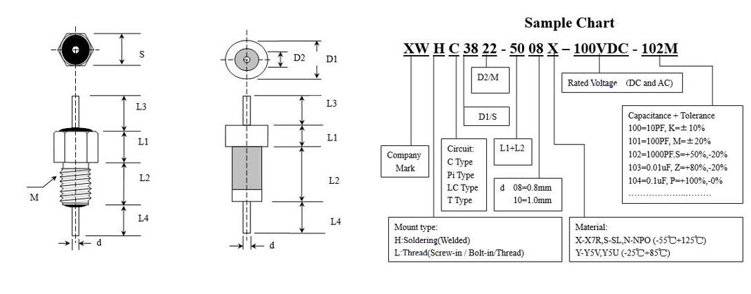
For example:
Soldering Mount Feedthrough Capacitor (H)
C type Circuit (C)
D1 is 3.8mm (38)
D2 is 2.2mm (22)
Body width(L1:1.5mm+L2:3.5mm) is 5.0mm (50)
Lead dia(d) is 0.8mm (08)
Ceramic Material: X7R (X)
Rated voltage is100VDC, (100VDC)
Capacitance is 1000pF (102)
Capacitance tolerance is +80%/-20% (Z)
Together them,so get out: XWHC3822-5008X-100VDC-102Z
Note:
1.Please offer us part number and order quantity.
2.Custom design is available.
3.Free samples are supplied.

2. Part of Applications
- Energy Management Systems
- Computers
- Automatic Lighting
- AM Radio Equipment
- Factory Automation Equipment
- Implantable Medical Devices(Cochlear Implants,Cardiac Pacemakers,etc.)
- Military / Space Electronic Modules
- Radio Controls
- Telecommunications
- Televisions and Monitors
- Laboratory Equipment
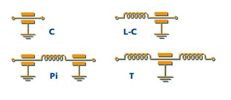
3. Electrical Configuration:
A number of different electrical configurations are available in EMI filters,including the common types shown opposite.A single element filter(a capacitor or an inductor) theoretically provides an insertion loss characteristic of 20dB per decade,a dual element filter(capacitor and inductor) 40dB per decade whilst a triple element filter(Pi or T configuration) theoretically yields 60dB per decade.In practise,the insertion loss curves do not exactly match the predictions.and the data of electrical configuration is made primarily on the source and load impedances and may also be influenced by the level of attenuation required at various frequencies.
C Filter
This is a feedthrough capacitor with low(hardly) inductance.It shunts high frequency noise to ground and is suitable for use with a high impedance source and load.
LC Filter
This is an EMI filter with an inductance element in combination with a capacitor.It is commonly used in a circuit with a low impedance source and a high impedance load(or vice versa).
Pi Filter
This is an EMI filter with 2 capacitors and an inductive element between them.Ideally,it should be used where both source and load impedances are high.
T Filter
This is an EMI filter with 2 series inductive elements separated by one feedthrough capacitor.It is suitable for use where both source and load impedances are low.
4. Source and load impedances
Insertion loss figures are normally publishes for a 50 Ohms source and 50 Ohms load circuit.In practice the impedance values will probably be very different,which could result in either an increase or decrease in insertion loss.The electrical configuration of the filter(the capacitor/inductor combination) should be chosen to optimize the filter performance for that particular source/load impedance situation.An estimate of insertion loss for source and load impendence other than 50 Ohms can be supplied.Please contact our Sales Office.
5. Bolt Mount EMI Filter ( Bolt-in Filter )
Bolt Mount EMI Filters provide increased filtering in HF through MICROWAVE frequency spectrums from 100KHz through 10 GHz.The larger hex size means that much higher values of capacitance are available and that a 125 VAC/400 Hz rating in available in certain values.Also designed for mounting in a tapped bulkhead to with the standard nut and lock washer provided,it is optimum in medium to low impedance cricuits where significant amounts of capacitance to ground can be tolerated.In the “L”and “Pi” section versions an internal ferrite bead element provide both inductance and series resistance(lossy characteristic) which improves the insertion loss rolloff to 40dB and 60dB per decade respectively.
Note:
- Pi design offers steeper insertion loss rolloff.
- Features rugged monolithic discoidal capacitor construction.
- Epoxy seal on both ends.
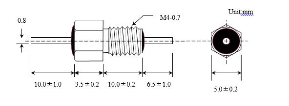
Example:
XWLPi5040-13508X-100VDC -332Z
Technical parameter:
- Rated Voltage:100VDC
- Rated Current:10A
- Capacitance and Tolerance:3300PF +80%,-20% Z
- Insulation Resistor:>10000M Ohms
- Dissipate Factor:<3.5%
- Withstand Voltage:200VDC, one minute No Short Circuit,No Failure.
- Temperature Feature:-55 ℃ to +125 ℃
- Circuit :Pi Type
- Dimension Tolerance:L±0.5mm, W±0.2mm, M / d±0.1mm
The thread stocks we have M2.5,M3,M4,M5,M6,M8,M10 and UNC UNF as follows:
1.Just the dimension above the chart,it is our stocks in our house,and if you have your own dimension request,you can email us that we will open the new models for you,sure,as long as you have the large quantity,we will open the free one for you,if you have order a little,you have to pay some model fee.
2.Voltage: As the above chart,it is only marks the DC,In fact,we also can produce the AC for you as long as your appliance need it.
3.Planting number on the surface,please show your word details.
Capacitance: measured @ 1KHz and .1 to 1 VRMS,25 ℃
Dissipation factor: 3.5% max.
Insulation Resistance:10,000 Mohms min. @25 ℃, WVDC;1000 Mohms min. @ 125 ℃WVDC
Dielectric withstanding voltage: 200% of WVDC min.
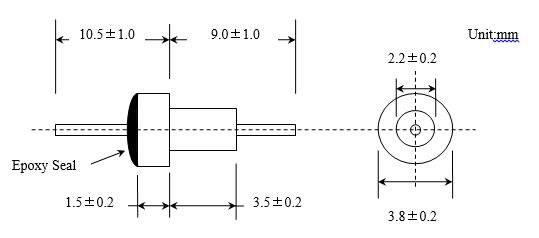
6. Solder Mount EMI Filter (Solder-in Filter )
Solder Mount EMI Filter is intended for use as a high reliability alternative a commonly available commercial filter type,Due to its smaller body diameter,capacitance is limited.It does provide effective filtering in the MICROWAVE frequency spectrum from 100MHz through 10GHz.Designed to be soldered into a package,bracket or bulkhead(and maintain hermeticity),it is ideal for high impedance circuits where large capacitance values are not practical.
Alternate lead lengths or special capacitance values are available upon request.
Custom package to bracket assemblies utilizing this feedthru can be furnished to your specifications.
Note:
1.Epoxy seal on both ends.
Example:
XWHC3822-5008X-100VDC -102Z
Technical parameter:
- Rated Voltage:100VDC
- Rated Current:7A
- Capacitance and Tolerance:1000PF+80%,-20%
- Insulation Resistor:>3000M Ohms
- Dissipation Factor:<3.5%
- Withstand Voltage:200VDC, one minute No Short Circuit,No Failure.
- Temperature Feature:-55 ℃ to +125 ℃
- Circuit Type:C Type
- Dimension Tolerance:L±0.5mm, D±0.2mm, d±0.1mm
The soldering parts we had a lot, please contact with us if you are interesting.
1.Just the dimension above the last chart,it is our stocks in our house;
2.Voltage:The above chart,it is only marks the DC,In fact,we also can produce the AC for you as long as your appliance need it;
3.About the plant number on the surface,you can told us what can we plant,we will do it according to your details;
4.If you only accept the Inch unit,we will do it for you too.
7. Multilayer EMI Filter Chips
.Feature and Appliance
1.Small volume,large capacitance,small capacitance change;
2.Used to manufacture kinds of EMI Filter and related components;
3.Used to prevent RF interference of by pass and flter,have some features of different rated voltage、kinds of temperature feature and outdrawing dimensions,so it fit for aerospace equipment,consumer electronic devices;
4.Temperature Feature:-55℃ to +125℃.
- Electrical Properties
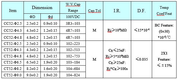
a.W.V.Cap Range:Working Voltage Capacitacne Range;
b.Cap.Tol:Capacitance Tolerance(M=+/-20%);
c.I.R.:Insulation Resistance;
d.D.F.:Dissipation Factor;
e.Temp Coef/Feat:Temperature Coefficient/Feature.
- Order samples:
CT52-Φ2.5-2X1-100VDC-223-M
① ② ③ ④ ⑤ ⑥
①Item ②Dimension Part ③Temperature Coefficient/Feature
④Rated Voltage(W.V.:Working Voltage) ⑤Capacitance ⑥Cap Tolerance
Notes:
- Chips’ Thickness,up to the clients request.
- Custom design is available.
Application Guidelines
8. Insertion Loss Measurement
Insertion Loss(IL) is a measure of the effectiveness of a filter.it is defined as the ratio of the voltage(E1) across the circuit load without the filter and the voltage(E2) across the load with the filter.Since insertion loss is dependent on the source and load impedance in which the filter is to be used,IL measurement are defined for a matched 50ohms system.The insertion loss is measure in decibels(dB) and defined as follows:
IL(dB) = 20 log [E1 / E2]
Circuit Impedance VS. Insertion loss
In practical circuit applications the source and load impedances may be quite different from 50ohms.If these impedance are known,Xiangwei Engineering can provide information on the expected Insertion Loss or an estimate can be made using the following formula:
IL(dB)=20log[1+ZsZl / Zt (Zs+ Zl)]
Where Zs=Source impedance in ohms,Zl=Load impedance in ohms, Zt=Transfer impedance in 50ohms.
Example:
- System source and load impedance are 100ohms and 600ohms respectively.
- Selected filter has insertion loss of 50dB at 100 MHz in a 50ohms system.
- From the IL VS Transfer Impedance curve(right) the transfer impedance is 0.08ohmz.
- IL = 20log[1+100*600 / 0.08*(100+600)] = 20 log 1072 = 61dB
9. Miniature EMI Filter
XWHC4033-2808S-100VDC-101M
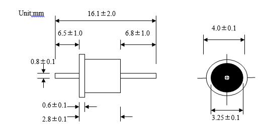
Technical parameter:
- Rated Voltage:100VDC
- Rated Current:5A
- Capacitance and Tolerance:100PF ±20%
- Insulation Resistor:>3000M Ohms
- Dissipate Factor:<3.5%
- Withstand Voltage:200VDC, one minute No Short Circuit,No Failure.
- Temperature Feature:-55 ℃ to +125 ℃
- Circuit Type:C Type
The capacitance will be arranged from 10PF to 1uF,the high capacitance only has low rated voltage,and the different materials(SL,NPO,X7R Y5U Y5V Y5P…) depend on the capacitors electric feature.
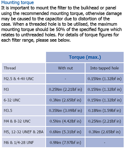
10. MAX Mounting Torque:
EMI Filter dielectric feature
EMI Filter:
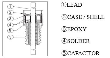
The capacitor used in Filter just as ceramic EMI filter.It also called Feed-thru Capacitors,Feed Through Capacitor,Feed-thru Filter,Feed Through Filter,Feed-thru Condenser,EMI Feedthru. because of its physical structure.
Feed-thru Capacitor’s inductance smaller than usual capacitor,so resonance frequency by itself are high.meanwhile,it prevents the high frequency signal direct couple from input to output for Feed Through design.It supply better depressioneffect during frequency 1GHz because of low-pass together with high-cut.
It is the most simple of feed through structure that connect internal and external electrode with ceramic form one(C type) or two capacitor(Pi type).The capacitance arrange from 10PF to 4700PF,the rated voltage can achieve 2000VDC.Discoidal Capacitor didn’t show appearent resonance frequency by itself at 10GHz,because it has the coaxial strcuture.
Feed-thru Capacitor’s dielectric is ceramic,but ceramic capacitor’s capacitance will change by environmental temperaturechangable,capacitance changable will influence filter’s cut-off coefficient of filter.The ceramic capacitor dielectric fix itsself capacitance temperature change.So select the adequate ceramic dielectric is very important.usual ceramic dielectric and its capacitance temperature change as follows:
| Dielectric Feature |
COG(NPO) | X7R | Z5U | Y5V | |
| super stable | stable | usual | |||
| Working Temperature | -55℃—+125℃ | -55℃—+125℃ | -10℃—+85℃ | -30℃—+85℃ | |
| Cap. Temp. Change(max) | 0±30ppm/℃ | ±15% | -22%—+56% | -22%—+82% | |
| Insulation Resistor(IR) | ≥104MΩ | Cr ≤ 25nF IR ≤ 4000MΩ Cr ≤ 25nF IR* ≤ 100S |
|||
| Dissiaption Factor(tanб) | Cr>50pF≤0.015 Cr≤50pF≤0.015 (15/Cr+0.7) |
<0.025 | <0.030 | 0.050 | |
| Dielectric Strength |
working voltage | apply working voltage times(apply time 5 seconds,current 50max) | |||
| 200V | X2.5 | X2.5 | X2.5 | X2.5 | |
| 500V | X1.5 | X1.5 | X1.5 | — | |
| >1KV | X1.5 | X1.25 | — | — | |
| Digestion Decimal Logarithm Time |
0 | 1% | 6% | 6% | |
Filter Inductor:
Filter inductor is used to ferrite materials,it can get together with the Feed-thru Capacitors conveniently,form the composite filter,in the filed of high characteristic filter,it also use wire-wound inductance.one point:Ferrite materials will appear magnetic saturation in high current,and reduce the filter function.
Filter Installation type:
H:Solder-in type Filter L:Screw type Filter
EMI/RFI Filters feature and application:
Solder-in Filters:
 * Solder-in filters is the ideal component of the small stall space.
* Small dimension:use the space effectively;
* Rated Voltage: can achieve 750VDC;
* Circuit type:C type、Pi type、L type.
* Certification:MIL-F-15733 QPL and MIL-C-11015(CK99)
Epoxy seal bolt-in filters:
* The recommended nut and washer fix on the screw hole space convenient for epoxy seal bolt-in filter;
* It supply the good envirenmental protection both the two ends epoxy seal.
* Application:signal、data wire and DC switch wire filter;specially the miniature press-in and bolt-in install used in the un-soldering space,it fit for the microwave and high pass.
* Rated voltage:can achieve 4000VDC/250VAC
* Circuit type:C type、L type、Pi type
* Certification:MIL-F-15733
High Current,High Voltage epoxy seal filters:
* Application:High current filters used in high current switch power、DC charge system;
High voltage filters used in high voltage power、the stable bolt structure fix easy.
* Feature:High current can achieve 100Amps
* Rated voltage:can achieve 4000VDC and 250VAC@400Hz
Glass seal miniature EMI Filters:
* This filter use the glass seal、has the nice EMI filter feature;it is the best choice that it need the high stable filter in the rugged environment,will high frequency high stable EMI filter during 10KHz to 10GHz,glass seal series anti-moist、anti-corrosive、protect the filter nicely in the field of military affairs.
* Application:power、signal wire、rocket ignition system、plane、military telecommunication、medical equipment、multiple-stage filter;
* Stable:According to MIL-F-15733 and MIL-F-28861 standard manufacture、and fit for QPL request;the level of “S” aerospace usage.
* Feature:Insertion Loss spread from 1MHz to 18GHz
* Capacitance and Temp.Feature:1.5uF NPO、X7R、Z5U
* Temperature arrange:-55℃-+125℃ Max Voltage: 4000VDC 250VAC@400Hz Max current:30Amps
EMI(Electromagnetic Interference) Filters, also known as RFI (Radio Frequency Interference) Filters, basically are passive electronic devices that are used to suppress conducted interference that is found or a signal or power line. Electromagnetic Interference(EMI) is unacceptable electromagnetic emissions,natural or man-made, which cause the degradation or malfunction of electronic or electrical equipment. Radio Frequency Interference(RFI) is detrimental electrical energy in the frequency range,which is for the specific transmitted radio frequency. Major sources of EMI and RFI include microprocessors,switching power supplies,AC motors,and electrical power cords (which basically act as an antenna).
As mentioned previously,an EMI/RFI Filter is a passive electronic device (comprised of multiple components) for suppressing conducted interference found on any signal or power line.An EMI/RFI Filter will suppress the interference created by other equipment and the interference of the module or system itself,with the desired result being improvement to the immunity from EMI/RFI signals in the surrounding setting.EMI Filters can be found both in plastic as well as metal housings,in stand-alone,desktop or module configurations.
An EMI Filter works by presenting a significantly higher resistance to higher frequency content.In other words,the low pass design of the EMI/RFI Filter (the combination of shunting capacitors and series inductors) results in the restriction/impeding of the flow of high frequency signals,electively shorting it to ground.The final result of the EMI Filter is that it reduces and attenuates the unwanted signal strength,thereby having a minimal effect on other components or devices.EMI Filters are gauged by specifications including insertion loss,voltage rating,and current rating.In addition,there are numerous approval authorities and specifications,including UL,CSA,VDE and military specification.